RoboCube home

RoboCube


The Robocube has been designed from 1997-2000 at the VUB AI Lab by Dr. Thomas Walle
It is currently used by some research groups including the RIDS (Roboter in der Schule) project and the IUB Robotics group
Robocube's Operating System ''CubeOS'' can be found here
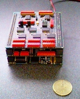
One main goal of the architecture is to allow the on-board implementation of as many robot behaviors as possible. Therefore, RoboCube provides quite some computation power and memory within the space-constraints. In addition, RoboCube is layed out to deal with various sensors and motors, radio-communication, and the option of high-resolution on-board vision.

Main features

  • open bus architecture
  • MC68332 CPU running at 16MHz
  • 256kB SRAM main memory
  • 128kB EPROM
  • 24 analog/digital (A/D) converter,
  • 6 digital/analog (D/A) converter,
  • 16 binary Input/Output (binI/O),
  • 5 binary Inputs,
  • 10 timer channels (TPC),
  • 3 DC-motor controller with pulse-accumulation (PAC), and
  • an intelligent active InfraRed (aIR) subsystem.
An important aspect is that RoboCube's onboard software core supports an easy handling of these ports in combination with common sensors and motors. This means that it is possible to PlugAndPlay various components, which can be accessed in a high-level manner in software. RoboCube runs the Process Description Language (PDL) which combines C with special constructs facilitating behavioral control through networks of dynamical processes. For more information look to:
  1. Hardware
  2. BIOS
  3. Connectors
  4. Assembly of the stacking conncetors
  5. pdf sources of the used components
  6. Schematics

RoboCube Version 2.0

Currently, we are working on a new version of the RoboCube platform. New features include:  Whereas the BDM interface allows for a much better debugging, it also serves as a facility to program the now available Flash-EPROM from scratch. To do so, we developped a simple linux tool, called the BDM monitor to perform simple debugging tasks like e.g. reading processor status, reading and writing memory locations, downloading S-record files and last but not least programming and erasing our flash EPROMs. All source files are freely available here

The embedding of the DUART and the two I2C busmaster chips allows a much higher CPU frequency, i.e. 25MHz. Additionally, 16 direct memory mapped binary outputs could be inserted. 

On top of that, an additional board was designed. It hosts a MC68882 FPU chip running at 25MHz and implements 16MB of DRAM. Since the whole physical address space is 16MB, only 13MB are accessible. 

Again, the pdf sources of the used components can be retrieved here and the schematics can be seen here.